european narrow gauge mODULAR RAILWAYS AUSTRALIA

Welcome to EuronaMo Australia. This standard is based on one published by PaulRhB on RMweb, and has successfully been used with a group turning up, assembling a railway and running it within a few hours. The standard is defined by an end connector plate, a scenic colour for the transition between modules, a track height, and DCC control.
The theme regarding scale is HOe and the scenery, buildings, rollingstock and locomotives are freelance prototype Continental Europe narrow-gauge (era non-specific), and should not be diverged from.
DCC:
The layout will use Digital Command Control (DCC) to run trains. The wiring is designed to be compatible with mainstream DCC systems (e.g. Digitrax, NCE or Lenz) by simply connecting the two BUS wires that run underneath the layout to a Command Station.
A member of the group will provide a DCC Command Station capable of supporting multiple throttles by Wi-Fi.
Modules:
Modules are the individual sections of layout that are joined together to create a working model railway.
Modules may be any shape, length or width, but must not be wider than the endplate (see below) where they meet other modules. Modules should also adhere to the track, scenic, and electrical standards.

Backscenes are not included in the standard, and all modules are required to be operational from both sides.
Modules must be free standing without relying on other modules for support, but may consist of multiple boards to form a module, how they are supported at intermediate ends is up to the builder.

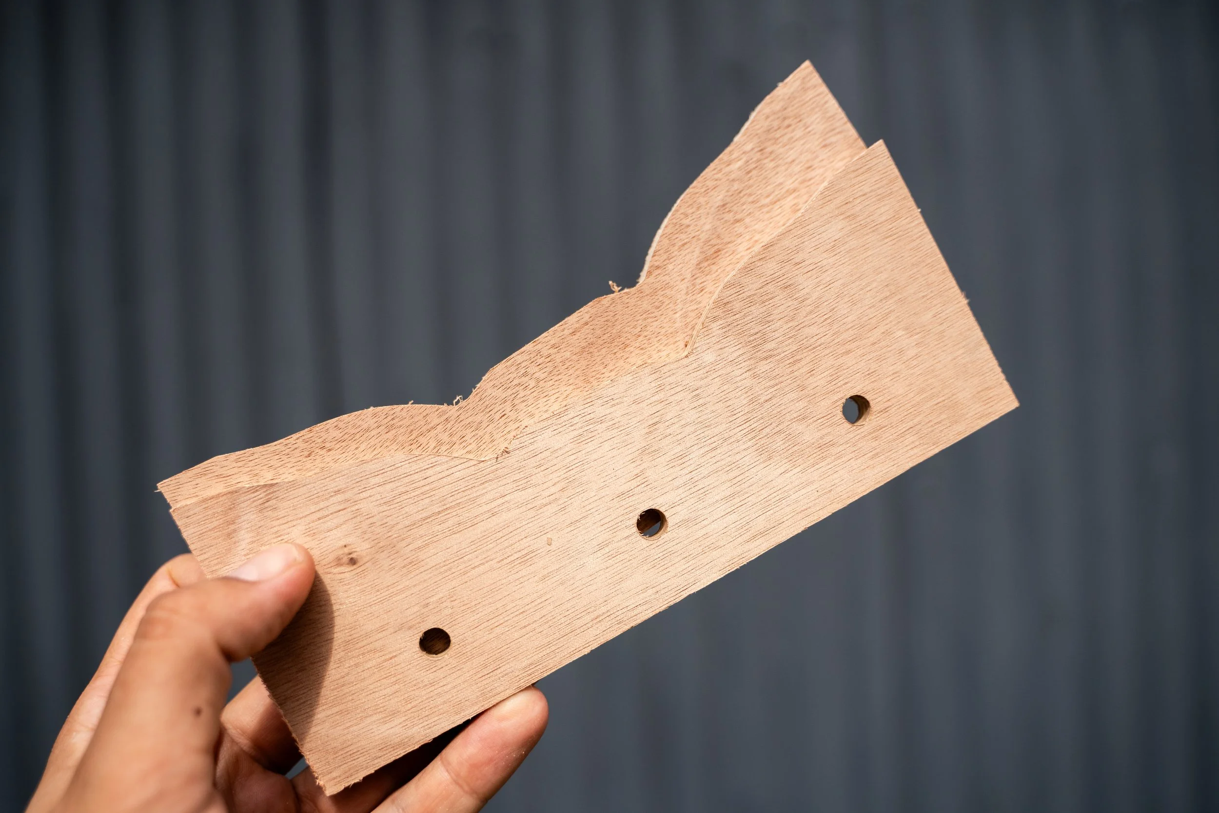
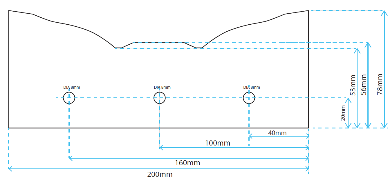
Endplates:
The modules will be clamped together for maximum flexibility and compatibility. The end profile allows for a 3mm cork roadbed, that is produced by companies such as AMRI as Strips for N Scale (1-0404) and are readily available from most hobby stores, however brand isn’t as important as height.
Endplates should be made the template provided, and use 9mm thick Plywood for rigidity. Endplates are available pre-fabricated from the Will James Railways website.
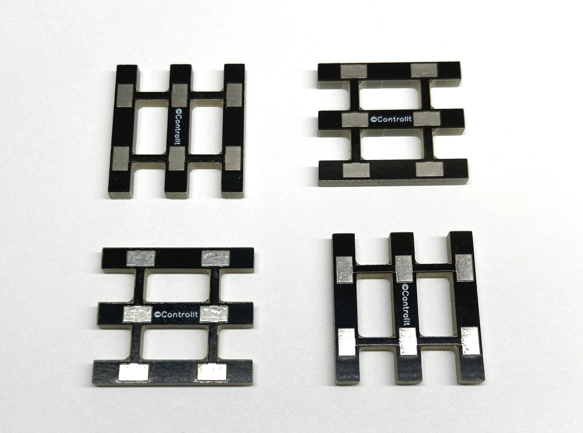
The rails at the joins between modules should use either copper clad sleepers or 009 scale PCB sleepers, such as those available from ControlIt. Both are required to be glued at the end of the module.
Track Standards:
Peco ‘Mainline’ or ‘Crazy’ 009 scale track is to be used. Track is required to be at a height of 1000mm (to the top of the rail) from the floor, and all mainline tracks must maintain this height throughout the module. For optimal running performance, gradients are only permitted (though not encouraged) in limited quantities in yards/sidings, and only where prototypically appropriate (e.g. transfer yards or quarries/mines).
The first 20mm of track at the module end must be straight to prevent angles at the join. Minimum radius on the mainline is 21 inches. Tracksetta tools are useful for this process.
Minimum radius for sidings is 9 inches. If you want to use sharper radii for industrial tracks or sidings, then please supply a shunter capable of traversing these sharper curves.
It is recommended for any station loop to have sufficient space to fit three Peco L&B coaches (480mm), with a minimum space allowance of two coaches (320mm).
The recommended spacing between tracks is 40mm, minimum 35mm. Headshunts for locos are preferred to be a minimum of 140mm, as it allows larger locos such as to run around without a shunt release.
Note: Kato Unitrack is not to be used.
Points:
Points on the mainline should be Peco medium radius (SL-E496/SL-E495/SL-E497) or small radius (SL-E491/SL-E492) Electrofrog points. Set track and insulfrog points are not to be used.
Points are to be changed by hand, using slide switches or push rods under the module. Points must also be compatible with DCC, switching the frog polarity on Electrofrog points. All methods of switching points must be accessible from both sides of the module without requiring operators to reach over the module. A recommended approach is to use push rods embedded in holes in the side of the module (see examples below).

Powered point motors can be used but power is to be supplied by an external source and be compatible with all mainstream DCC systems. Motorised points are discouraged for the purpose of maintaining maximum compatibility and operational flexibility.
Recommended Non-Powered Point Motor:
The recommended approach is to use Blue Point turn out controls (40018) by New Rail Models.
These point motors are mounted underneath the module and can be connected to push rods linking to each side of the module, switching the frog polarity as the points are thrown.

Scenery Standards:
Ballast colour should be Grey Blend: Medium (WB94 or WB1394) or Fine (WB1393) by Woodland Scenics. Weathering the ballast is recommended, but not necessary.
Loading Gauge:
The required clearance for all scenic objects around the track and maximum size of rollingstock is defined in the below diagram
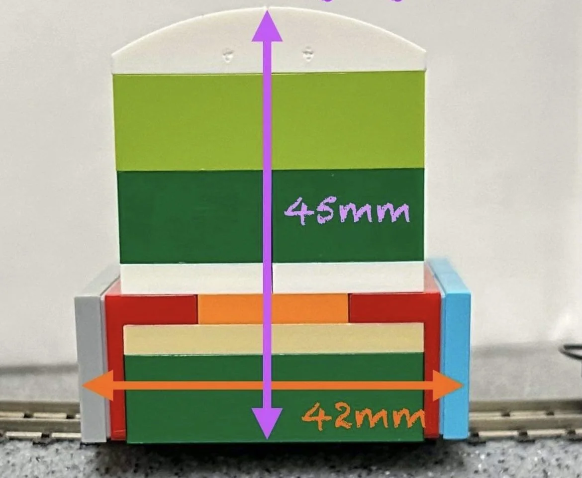
Image courtesy of Salisbury ASC on Flickr
Minimum height for scenery from the top of the railhead should be 45mm.
Module Connection:
Modules are electrically connected by sockets at each end with a through BUS wire. Rails are not to be used as the main power connection from one end of a module to the other. The track should be connected by dropper wires to the BUS wires running under the module. Mains cable or 6amp wire is suitable for the main BUS wires.
Every section of track should be wired to the power bus for a reliable and solid connection.

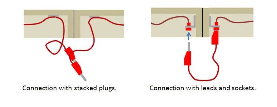
Wire Colours are not crucial as the modules are reversible.
These standards are current as of October 2024.
For any other information or questions please email.